Anyone looking to install or maintain a reliable power system in their campervan must first understand the basics of a DC-to-DC charger wiring diagram. Even if a professional installs your van electrics, you must know your system inside out—especially when you're off-grid in the wilderness and the only one to troubleshoot and fix any issues.
We break down what a DC-DC charger does, how it works, and the critical components in setting up a stable and efficient system.
BUILD YOUR OWN CAMPERVAN ELECTRIC SYSTEM IN MINUTES
Understanding the Basics of DC-DC Charger Wiring
Understanding the basics is essential before attempting to install a DC-DC charger. This section will explain what a DC-DC charger does, how it works, and the key components you need for a reliable system. With these fundamentals, you'll be better equipped to handle wiring diagrams and troubleshooting in later sections.
What is a DC-DC charger, and how does it work?
A DC-DC charger converts power from your vehicle's alternator or battery into a stable charge for a secondary/auxiliary battery. It manages voltage differences and ensures the auxiliary battery charges efficiently without overloading the system. Regulating the charge protects your batteries and prolongs their lifespan.
Key terms and components of a DC-DC charging system
- The DC-DC charger unit controls the voltage from the main to the auxiliary battery, ensuring a consistent and safe charge.
- Fuses and fuse holders protect your wiring and components by breaking the circuit if a fault occurs, preventing potential damage to the system.
- Positive and negative cables connect the batteries and components, with the positive carrying power and the negative ensuring proper grounding.
- Busbars distribute power efficiently to different parts of the system, reducing the need for multiple connections and minimising voltage loss.
- Your vehicle's starter battery is responsible for starting the engine. The DC-DC charger draws power from this battery to charge the auxiliary battery without draining the main battery.
- The leisure battery powers your appliances or electrical systems when the engine is off. The DC-DC charger ensures it charges while protecting it from overcharging.
A proper leisure battery setup is essential to ensure your DC-DC charger works efficiently and delivers consistent performance when you're off-grid.
(optional depending on DC-DC Charger) An isolator separates the main and auxiliary batteries, ensuring the main battery starts the vehicle and the auxiliary battery handles everything else. Isolators are critical for dual-battery setups to avoid draining the main battery.
Wiring Diagram for a Basic DC-DC Charger Setup
Correct wiring of a DC-DC charger is critical for a reliable campervan, motorhome, or leisure vehicle power system. Single-battery and dual-battery configurations are the most common for mobile homes. We've included helpful diagrams and considerations for installing.
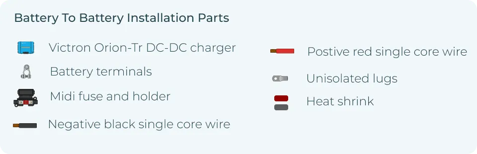
Single battery DC-DC charger setup
Your DC-DC charger connects directly to the vehicle's main battery in a single battery setup. The charger regulates the voltage and provides a steady charge to the auxiliary battery, which powers your appliances.
Considerations for single-battery setups:
- Ensure proper fuse placement between the main battery and the charger to prevent damage.
- Choose the correct cable gauge to handle the current load and avoid overheating.
- Proper grounding is essential to prevent electrical faults.
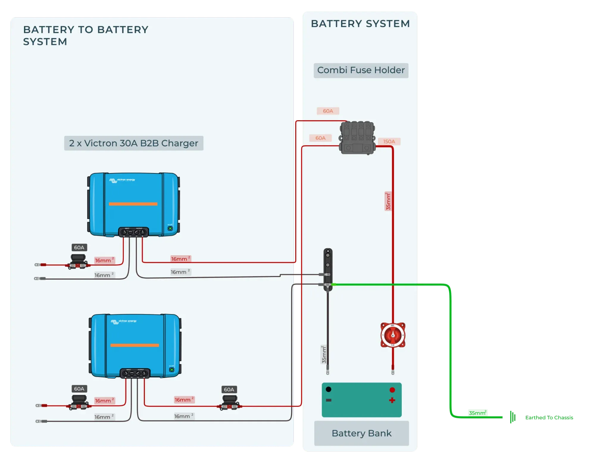
Dual battery DC-DC charger setup
The dual battery setup introduces a second auxiliary battery, often with an isolator. This isolator ensures the system uses the main battery to start the vehicle while the auxiliary battery powers everything else. When the van is running, the alternator charges both batteries through the DC-DC charger.

Benefits and challenges of dual-battery systems:
- Keeps your main battery separate, ensuring the vehicle can start even if you drain the auxiliary battery.
- Dual battery setups are ideal for larger power needs but require more wiring, including an isolator and fuses.
- Managing voltage drops across longer cable runs becomes more important with this setup.
Wiring a DC-DC Charger with a Smart Alternator
Unlike regular alternators that constantly produce the same voltage, a smart alternator adjusts its output based on the vehicle's power needs. This efficiency helps reduce fuel consumption and emissions.
However, the fluctuating voltage can complicate charging an auxiliary battery, making wiring a DC-DC charger essential for stable power delivery.
Understanding voltage regulation in smart alternators
- Smart alternators lower their voltage output when demand is low, which saves energy but impacts battery charging.
- The DC-DC charger stabilises this by regulating the voltage for the auxiliary battery, avoiding undercharging.
- Your batteries might not charge correctly without proper regulation, especially during longer trips.
Luckily, the Victron DC-DC SMart Charger takes care of all of this. It uses adaptive charging to work with your smart alternator to ensure that your battery gets topped up when you drive.
Troubleshooting common wiring issues with smart alternators
Voltage drop:
Use a voltmeter to measure the voltage at both ends of the cable between the main battery and the DC-DC charger. If you see a significant drop (more than 0.5V) between the two points, it indicates the cable is too thin or there's a poor connection. Fix by upgrading to a thicker cable or tightening/replacing any loose connectors.
Undercharging:
Check the voltage at the ignition trigger input of the DC-DC charger with a voltmeter. If it's not getting a signal when the engine is running (typically around 12V), the charger won't activate. Trace the wiring back to the ignition source and look for loose or faulty connections. You may need to repair or replace damaged wiring.
Overheating:
Measure the voltage at the DC-DC charger's input and output terminals with a voltmeter. If the input voltage fluctuates significantly (dipping well below 12V), the alternator may drop its output too much. This dipping can cause the charger to overheat from trying to compensate. Fix by checking the smart alternator settings or adding a voltage-sensitive relay (VSR) to stabilise the input voltage.
GET A FREE WIRING DIAGRAM WITH EVERY PURCHASE—BUILD YOUR ULTIMATE CAMPERVAN ELECTRIC SYSTEM IN MINUTES!
Essential Wiring Components for a DC-DC Charger Explained
Understanding the essential wiring components of a DC-DC charger is crucial for building a reliable and safe power system to avoid voltage drops, overheating, or potential damage to your batteries and components.
Cables: Choosing the correct gauge for your setup
Choosing the correct cable gauge minimises voltage drop and ensures efficient power delivery. Larger cables reduce resistance and prevent overheating, especially for longer runs.
Cable sizing and voltage drop considerations:
- Use thicker cables for long runs or high-current setups to prevent voltage loss.
- Use a voltmeter to measure the voltage drop across the cable. Place the probes at both ends of the cable while the system is running. The difference between the two readings is your voltage drop. To keep your system efficient, aim for no more than a 3% drop.
- Refer to a cable sizing chart based on your system's amperage and distance to choose the appropriate gauge.
Fuses: Why proper fuse selection is critical
Fuses protect wiring and components from overcurrent, which can cause overheating or fire. If the current exceeds a safe level, they break the circuit.
Types of fuses (midi, ANL) and their roles in protecting your system:
- Midi fuses: Compact and commonly used for lower-amperage circuits, they protect smaller components.
- ANL fuses: Designed for high-current setups, they protect your main and auxiliary batteries in a dual-battery system.
- Always place fuses close to your power source (battery) to protect the wiring.
Grounding: Ensuring a safe and efficient circuit
Proper grounding ensures your system runs efficiently and avoids dangerous electrical faults. Grounding completes the circuit and provides a path for excess current to discharge safely.
Best practices for grounding your DC-DC system:
- Ground cables should be as short as possible and connected to clean, unpainted metal surfaces.
- Use heavy-duty ground cables that match the size of your power cables to prevent imbalances.
- Regularly check grounding points for corrosion or loose connections, as poor grounding can lead to voltage spikes or system failure.
Advanced Wiring Techniques for DC-DC Chargers
This section is for those who want to take their DC-DC charger setup a step further, especially if you're handling more complex installations. If you're a DIYer, understanding advanced wiring techniques like series vs. parallel configurations and preventing voltage drops is crucial. If hiring a professional, this information will help you ask the right questions and ensure they wire your system efficiently.
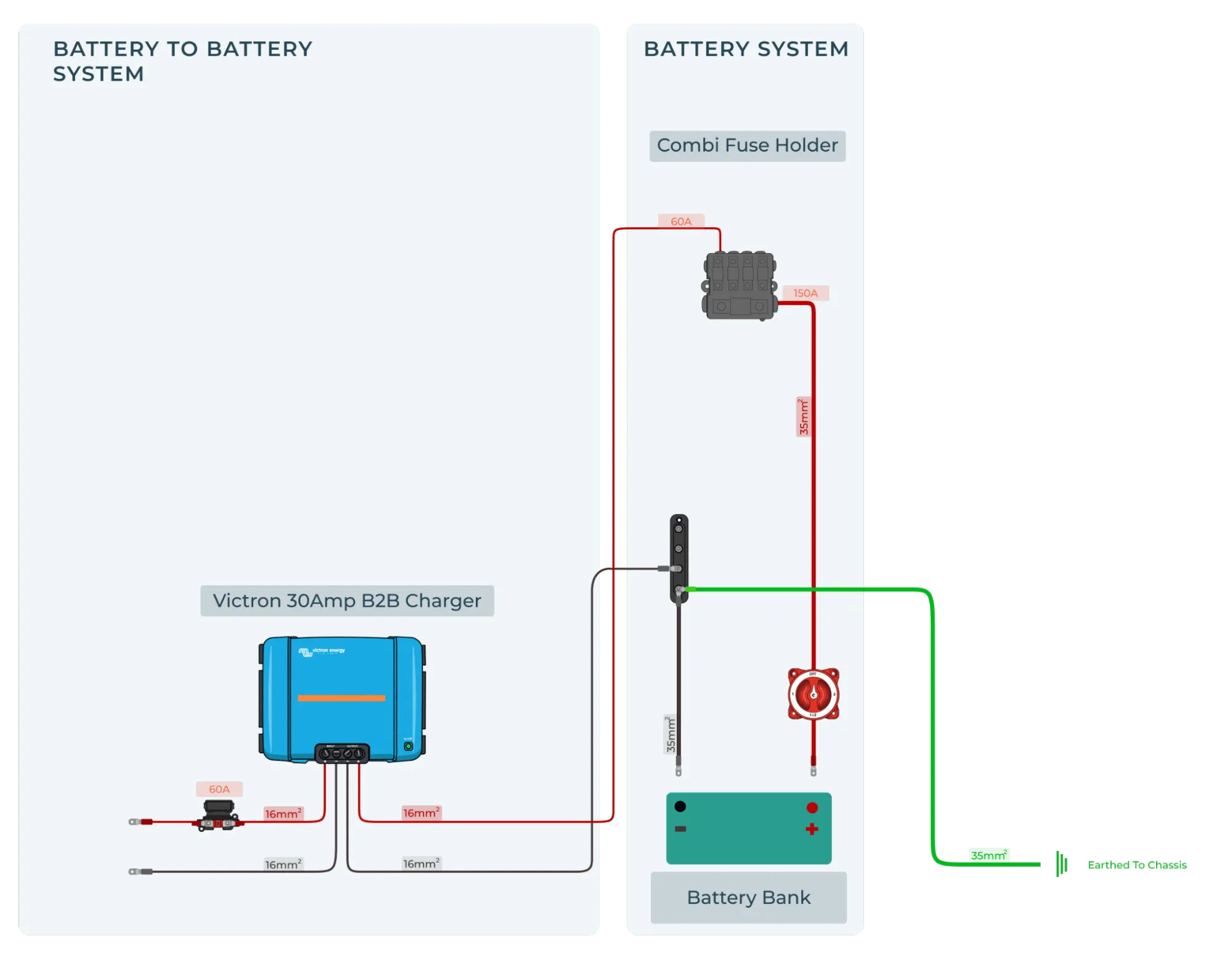
I have a 24V Starter Battery and 12V Leisure Battery.
Some larger vans or trucks have a 24V starter battery for those bigger engines out there. Before you buy a DC-DC charger, you will want to double check what voltage your starter battery is - easily done using your trusted voltmeter. If you have a 24V starter battery, you will want to purchase a 24 - 12 Victron DC DC charger.

I Have a 12V Starter Battery and a 24V Leisure Battery
So you have checked, and your van has a 12V starter battery. It makes sense; most do. However, you have some pretty hefty power demands and, therefore, have a 24V battery bank—either two 12V batteries connected in series or a native 24V battery. You will need to buy the correct DC-DC charger. You will want one that converts 12V to 24V when you are driving. The Victron 12 | 24 Smart DC-DC charger does just that.

I Have a 24V Starter Battery and a 24V Leisure Battery
You are a van life goliath and have a big engine and significant power needs. There is only one product for you - you guessed it right, the Victron 24 | 24 Smart DC-DC charger.
How to prevent voltage drops in long cable runs
Voltage drop happens when power travels long distances through cables, especially with higher current loads. This longer cable length results in inefficient charging and poor system performance.
How to calculate voltage drop over long cable runs
Use a voltmeter to check the voltage at both ends of the cable while the system is running. The difference is your voltage drop. Alternatively, you can use an online voltage drop calculator by inputting your cable length, gauge, and load (amperage).
Best practices for minimising voltage loss
- Use the thickest cable gauge possible for long runs to reduce resistance and voltage loss.
- Keep cable runs as short as possible.
- Regularly check for corrosion or loose connections, which can increase resistance and further contribute to voltage drop.
Common Wiring Mistakes and How to Avoid Them
Even small wiring mistakes can lead to system failure, damage, or safety hazards. Whether you're doing the wiring yourself or overseeing a professional, recognising these common issues can save you a lot of trouble. Here's how to spot and fix your DC-DC charger setup's most common wiring mistakes.
Misconnecting positive and negative cables
Crossing positive and negative cables can seriously damage your charger, batteries, and electrical components. This mistake often blows fuses or damages sensitive electronics.
Consequences and how to fix the issue:
- Signs: Blown fuses, sparks, or no power when the system is switched on.
- How to fix: Use a voltmeter to check the polarity at key points. The positive cable should always show a voltage relative to the negative or ground. If you've misconnected them, power down the system immediately, swap the wires and replace any blown fuses.
Incorrect fuse sizing
Using the wrong fuse size can leave your system unprotected or cause constant fuse blowouts. Fuses protect your components from drawing too much current, so sizing them correctly is critical.
Why fuse sizing is critical and how to choose the right one:
- Signs of incorrect fuses: Frequent fuse blowouts or fuses that don't blow when there's a fault (leading to component damage).
- How to fix: Check the current draw of each part of your system using a voltmeter and choose a fuse rated slightly higher than the normal operating current. For example, if your system draws 30 amps, use a 35-amp fuse. Always install fuses as close to the power source as possible.
Poor grounding practices
Improper grounding can lead to inconsistent performance, voltage spikes, or electrical failure. Poor grounding is often due to weak connections or using a ground wire that is too thin.
Common grounding errors and how to correct them:
- Signs: Flickering appliances, voltage spikes, or irregular battery charging.
- How to fix: Inspect your ground connections to ensure they're clean, tight, and attached to bare metal. Remove any paint, rust, or dirt from the grounding point. Use a cable that matches the size of your positive cable to ensure a balanced current flow. Check with a volt meter that your ground connections are solid, and the voltage is stable across the system.
How to Use a Voltmeter for DC-DC Wiring Troubleshooting
Whether you're checking for voltage drops, undercharging, or grounding problems, a voltmeter helps pinpoint the issue quickly. Here's a step-by-step guide on using a voltmeter for the most common tasks in DC-DC wiring setups.
Checking voltage drop across cables
Voltage drop occurs when current travels through cables over long distances. Too much voltage drop leads to inefficient charging or power loss.
Steps:
- Set your voltmeter to the DC voltage setting.
- Place the positive probe at the source (main battery) and the negative probe at the destination (DC-DC charger or auxiliary battery).
- Record the voltage at both ends of the cable while the system is running. The difference between these readings is your voltage drop.
Example:
If you measure 13.8V at the main battery and 12.8V at the auxiliary battery, you have a voltage drop of 1V. In most setups, aim for less than a 0.5V drop. You can fix this by using thicker cables or shortening the cable run.
Testing polarity to avoid misconnections
Misconnecting positive and negative cables can damage your components. Always check polarity before finalising connections.
Steps:
- Set your voltmeter to DC voltage mode.
- Place the red probe on the suspected positive terminal and the black probe on the negative or ground.
- A positive voltage reading means the polarity is correct. If the reading is negative, the wires are reversed.
Example:
If you expect 12V and the voltmeter shows -12V, you've crossed the positive and negative cables. Swap the connections immediately and check for any blown fuses.
Diagnosing undercharging issues
Undercharging usually happens when the alternator or ignition trigger isn't providing the correct voltage to the DC-DC charger.
Steps:
- Set your voltmeter to DC voltage mode.
- Place the positive probe on the ignition trigger wire and the negative probe to ground.
- When the engine is running, the voltage should read around 12V. If the reading is lower or zero, the ignition trigger isn't sending a signal.
Example:
If the reading is only 9V, the ignition trigger may be faulty or not wired correctly. Trace the wiring back to the ignition source and look for loose connections.
Measuring input and output voltage on the DC-DC charger
You'll need to measure the voltage at the input and output terminals to check if your DC-DC charger is receiving and delivering the correct voltage.
Steps:
- Set your voltmeter to DC voltage mode.
- Place the positive probe on the input terminal (connected to the main battery) and the negative probe to ground. Do the same for the output terminal (connected to the auxiliary battery).
- When running, the input voltage should match the main battery's output (typically 12.6–14.8V). The output voltage should be stable and close to 14V for charging.
Example:
If the input reads 12.6V but the output is below 13V, the DC-DC charger may not be functioning correctly. Check for any wiring issues or component faults.
Checking grounding connections
Poor grounding can lead to system instability or voltage spikes. A voltmeter helps confirm if your grounding points are solid.
Steps:
- Set your voltmeter to the continuity mode (or low resistance if your voltmeter lacks a continuity setting).
- Place one probe on the grounding point and the other on a clean, unpainted metal surface of the vehicle chassis.
- A low or zero reading indicates a good grounding. A high reading or no continuity means there's a grounding issue.
Example:
If you see resistance in the grounding wire, inspect the grounding point for corrosion, rust, or a loose connection. Clean or tighten the connection and re-test with the voltmeter.
If you're piecing together components yourself, it can quickly get complicated. That’s why many vanlifers choose a complete campervan battery system designed to work seamlessly with DC-DC chargers.